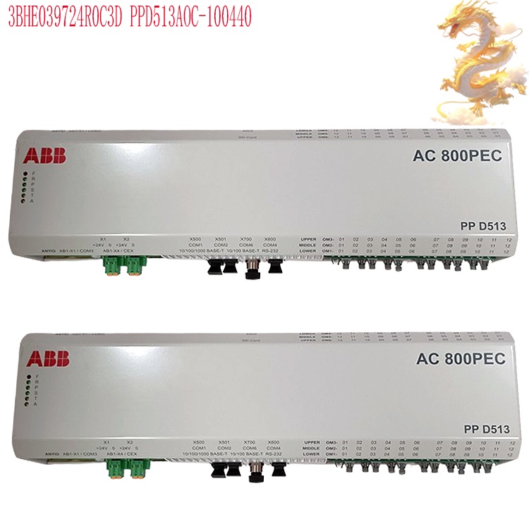
3BHE039724R2565 ABB AC800PEC Excitation Controller 3BHE039724R2565
As part of the ABB AC800PEC high-performance power electronics controller series, this unit serves as the core control module for the UNITROL excitation system. Built upon the scalable architecture of the ABB 800xA automation platform, it is specifically designed for the closed-loop regulation of excitation for synchronous generators and synchronous condensers. It functions as the primary computational hardware for excitation control systems within power plant excitation cabinets and is frequently utilized for spare part replacements or system retrofits for existing UNITROL installations. The controller employs a hardware architecture combining a CPU and an FPGA, with tasks organized into multiple cycle levels to accommodate the varying response-speed requirements of an excitation system. It continuously acquires analog and digital signals—such as generator terminal voltage, stator current, rotor excitation current, grid voltage, frequency, and circuit breaker status—and processes them through high-speed synchronous sampling, digital filtering, and coordinate transformation. By comparing the measured values against the voltage setpoint, the controller calculates the regulation deviation. It then executes an Automatic Voltage Regulation (AVR) algorithm, transmitting pulse commands via fiber optics to the thyristor-based power units. This adjusts the rotor excitation current in real time, ensuring stable, closed-loop control of the generator terminal voltage.

.jpg)
.jpg)
Many products have not yet been listed online; please contact us for information on additional items.
If there is a discrepancy between a product model and its displayed image, the model number shall take precedence. Please contact us if you would like to see specific product photos; we can arrange for them to be taken at our warehouse for verification.
We operate 76 shared warehouses globally, so it may occasionally take a few hours to provide you with an accurate response. We appreciate your understanding.
Rest assured, we will address your inquiries as quickly as possible.
3BHE039724R2565– Alternative Designations:
Excitation Processor Unit 3BHE039724R2565
Excitation I/O (Input/Output) Unit 3BHE039724R2565
Central Processing Unit (CPU) Module 3BHE039724R2565
I. Operating Principle
The 3BHE039724R2565 utilizes a CPU+FPGA hardware architecture, employing multi-level task cycles to accommodate the varying response-speed requirements of an excitation system. The controller continuously acquires analog and digital signals—such as generator terminal voltage, stator current, rotor excitation current, grid voltage, frequency, and circuit breaker status. Through high-speed synchronous sampling, digital filtering, and coordinate transformation, it compares measured values against voltage setpoints to calculate control deviations. It then executes an Automatic Voltage Regulation (AVR) algorithm, sending fiber-optic pulse commands to the excitation thyristor power unit. This adjusts the rotor excitation current in real-time, ensuring closed-loop, stable control of the generator terminal voltage. The controller features built-in logic for multiple regulation modes, allowing for bumpless switching between constant terminal voltage, constant reactive power, and constant power factor modes. It also incorporates a Power System Stabilizer (PSS) algorithm compliant with the IEEE 421.5 standard; in the event of grid disturbances or sudden load changes, it generates supplementary stabilizing signals to suppress low-frequency oscillations and enhance the transient stability of the unit when connected to the power grid. The system integrates a comprehensive suite of excitation limiting and protection logic—including over-excitation limiting, under-excitation limiting, stator current limiting, loss-of-excitation protection, and V/Hz limiting. It monitors the excitation circuit in real-time for abnormal conditions, executing alarms, limits, inversion, or field-suppression commands based on a defined priority hierarchy. Utilizing high-speed fiber-optic links for pulse transmission and synchronization, the system consolidates closed-loop regulation, sequential control, fault recording, and event sequence logging into a single hardware controller, achieving fully integrated excitation control.
II. Product Advantages
Hierarchical High-Speed Control: Designed to meet the stringent timing requirements of excitation systems, the platform employs a layered task execution structure. Closed-loop excitation control operates on a typical 400μs cycle; pulse generation and fiber-optic synchronization tasks can reach speeds as fast as 25ns; and standard sequential control logic operates at a 10ms level. This architecture balances rapid voltage regulation with stable logical processing, ensuring that the system’s response to grid short circuits or sudden load changes complies with both domestic and international grid-connection standards.

Dual-Channel Hot-Standby Redundancy: The system supports a configurable dual-channel (main/standby) synchronous architecture. In the event of a main controller failure, the system performs a bumpless transfer to the standby unit, ensuring continuous excitation regulation. Redundancy is also extended to power supplies, fiber-optic synchronization links, and communication channels, eliminating single points of failure and meeting the requirements for continuous, uninterrupted power generation.
Built-in Specialized Excitation Algorithm Library: The system comes with the standard UNITROL excitation algorithm package, featuring pre-standardized modules for AVR, PSS, various excitation limiters, and protection logic. It supports model development via Control Builder M and is compatible with MATLAB/Simulink simulations. This allows for the pre-verification of parameters within a simulated environment, significantly reducing the time required for on-site commissioning. Modular expansion with deep integration into the 800xA platform: Utilizing a backplane bus expansion scheme, the system allows for the flexible addition of sub-modules for analog data acquisition, digital I/O, and high-speed fiber-optic I/O. It integrates natively with the ABB 800xA DCS, supporting industrial communication protocols such as MMS and OPC UA. This enables supervisory monitoring, remote parameter viewing, and data uploading, making it well-suited for the automation architecture of an entire power plant.
High-precision timestamped fault recording and event logging: The system features built-in fault recording and sequence-of-events recording with millisecond-level time synchronization. It stores high-resolution sampling data throughout the entire duration of a disturbance. Following a fault, waveforms and event logs can be exported to facilitate the analysis of grid incidents and excitation characteristics, helping operations and maintenance personnel pinpoint issues.
Robust electromagnetic compatibility (EMC) for harsh power plant environments: Designed with industrial-grade ruggedized hardware, the system complies with power industry EMC standards, ensuring resilience against harmonics and strong electromagnetic interference within power plant cabinets. Its wide-temperature, dust-proof design supports long-term, continuous operation within excitation control cabinets.
III. Applicable Industries and Functions
Thermal Power Generation
Used in conjunction with UNITROL excitation systems for steam turbine-generator units, it stabilizes generator terminal voltage and dynamically adjusts the unit’s reactive power output in response to grid load fluctuations. Through the Power System Stabilizer (PSS), it suppresses low-frequency grid oscillations, ensuring stable grid-connected operation, reducing the risk of voltage limit violations or instability-induced trips, and enhancing the unit’s frequency and voltage regulation capabilities.
Hydropower and Pumped-Storage Power Generation
Designed for hydro-generator units and pumped-storage units, the system effectively manages demanding operational conditions—such as water hammer effects, rapid load changes, synchronous condenser operation, and black starts. It provides rapid excitation regulation to meet the requirements for peak shaving, voltage regulation, and synchronous condenser operation in hydropower facilities. Gas Turbines and Combined-Cycle Power Plants
Gas turbine units are characterized by frequent start-stop cycles and rapid operational changes. This controller provides fast-response excitation regulation, ensuring smooth grid synchronization and disconnection, stabilizing reactive power output, and supporting the flexible peak-shaving operational model of gas-fired power plants.
Synchronous Condensers and Renewable Energy Collection Stations
Serving as the primary excitation control hardware for synchronous condensers, this system dynamically manages reactive power flow. It provides voltage support for weak power grids and areas with concentrated renewable energy integration, enhancing grid voltage stability and mitigating voltage fluctuations at renewable energy sites.
Large-Scale Industrial Captive Power Plants
For synchronous generator units in sectors such as steel, coal-to-chemicals, general chemicals, and papermaking, this controller stabilizes the voltage of the internal plant busbar. It buffers the impact caused by the starting and stopping of high-power motors, ensures power quality within the industrial facility’s electrical network, and reduces the risk of unit disconnection or instability.
IV. Standard Operating Procedures
Important Prerequisite: Operations must be performed by engineers with professional qualifications in excitation systems, in strict compliance with electrical secondary-circuit safety regulations. Note that high-voltage CT (current transformer) and PT (potential transformer) circuits are classified as high-risk circuits.
Pre-power-up Checks: Ensure that all module latches are securely locked and that the backplane bus connections are reliable. Verify that fiber-optic end faces are clean and free from scratches or damage. Confirm that the power supply matches the rated DC 24V input. Check that the secondary wiring of instrument transformers is correct; ensure there is no risk of an open circuit for CTs or a short circuit for PTs, and verify that the protective grounding circuit is reliably connected.
Power-up Self-Test: Apply DC power to the controller. Observe the status indicator lights on the front panel and wait for the firmware to load and the hardware self-test process to complete. Once the self-test confirms no faults, use the ECT (Excitation Commissioning Tool) software or an 800xA operator station to verify the hardware version, channel status, and the status of fiber-optic communication links. Login and Parameter Configuration: Log in to the debugging interface using engineer-level credentials. Import the excitation parameter file for the generating unit, or manually enter the unit’s rated parameters, protection settings, and regulation mode parameters. Configure Power System Stabilizer (PSS) parameters and various excitation limit thresholds. Select the operating mode: constant voltage, constant reactive power, or constant power factor.
Static Open-Loop Debugging: Conduct open-loop tests while the unit is at a standstill. Verify the accuracy of analog signal sampling, the correctness of digital feedback and pulse outputs, and the proper operation of alarm and protection logic. Confirm the activation thresholds for protection settings.
No-Load Testing and Grid Connection: Initiate excitation for the unit and perform no-load voltage regulation tests to verify voltage regulation accuracy. Following synchronization with the grid, engage the automatic closed-loop excitation control. If conditions permit, enable the PSS function in stages, while continuously monitoring terminal voltage, reactive power, excitation current, and rotor current profiles.
Routine Monitoring and Redundancy Switching Tests: During normal operation, continuously monitor real-time parameters and alarm information via the operator station. For units with redundant configurations, periodically perform manual switching tests between the primary and backup channels under stable, low-risk operating conditions. Before maintenance, disable automatic regulation and switch to manual excitation mode.
Shutdown and Power-Down Procedure: Once the unit has been disconnected from the grid and the field has been de-energized, disable the automatic excitation regulation. Disconnect the excitation power unit circuit first, followed by the power supply to the controller.
Fault Data Export: In the event of a disturbance or fault alarm, log in to the ECT (Excitation Control Tool) software to export waveform records (oscillography data) and event sequence logs for subsequent fault analysis.
V. Precautions
Safety Rules for Secondary Circuits: Never leave CT (Current Transformer) secondary circuits open, and never short-circuit PT (Potential Transformer) secondary circuits. Although AC800PEC modules support hot-swapping, it is strictly prohibited to insert or remove modules, fiber-optic cables, or terminal blocks while the high-voltage secondary circuits of the excitation cabinet are energized. Such operations may only be performed after ensuring the equipment is de-energized, verified as dead, and properly grounded.
Firmware Version Management: Before any firmware upgrade, perform a full backup of excitation parameters and waveform recording data. The firmware version must be compatible with the entire UNITROL excitation system. For cross-version upgrades, conduct simulation verification beforehand to prevent algorithm mismatches that could lead to abnormal excitation regulation.

Fiber-Optic Link Maintenance: Fiber-optic cables serve as channels for high-speed pulse synchronization signals; avoid excessive bending, crushing, or stepping on them. Dust accumulation on the end faces can cause data packet loss or pulse distortion. Use only specialized fiber-optic cleaning wipes or tools; never touch the fiber-optic end faces with your hands.
Parameter Change Control: Modifications to parameters for the AVR (Automatic Voltage Regulator), PSS (Power System Stabilizer), excitation protection, and limiters are considered critical power system operations and must be performed under a "two-person supervision" protocol. Maintain written records of all parameter changes and conduct static or dynamic verification; arbitrary changes to setpoints without proper justification are strictly prohibited.
Thermal and Environmental Control: Ensure the excitation control cabinet is well-ventilated, dust-free, and dehumidified. Protect the equipment from high temperatures, condensation, and corrosive gases. Regularly clean the air filters inside the cabinet; overheating of modules can trigger protection interlocks or force a derating of the system.
Grounding Standards: Controller protective grounds and signal grounds must be connected to a single grounding point in strict accordance with the technical drawings. Ensure that grounding resistance meets power plant standards to prevent potential differences from introducing interference, which could lead to sampling drift or false alarms.
Redundant System Operation: Operating on a single channel for an extended period increases the risk of failure during a switchover; therefore, periodic tests of the primary-to-backup channel switchover must be performed. If an alarm regarding channel synchronization inconsistency occurs, prioritize troubleshooting the sampling circuits, fiber-optic synchronization links, and power supply circuits. Spare Parts Storage and Aging Management: The AC800PEC consists of precision power electronics circuit boards; therefore, spare units must be stored in a temperature-controlled, dry environment. For long-term storage, it is recommended to periodically power on the units for "aging" (burn-in) testing to prevent the degradation or failure of electrolytic capacitors that can occur during prolonged periods of inactivity.
Fault Handling Principles: In the event of a critical fault alarm during unit operation, follow the power plant’s operating procedures to reduce load, disconnect the unit from the grid, and de-excite the generator. Do not attempt to force the unit to remain excited by repeatedly restarting the controller, as this could escalate the incident and potentially lead to broader damage to the unit or the power grid.
Access Control: Commissioning, calibration, and parameter modification tasks are restricted to authorized engineers who are proficient with the ABB UNITROL+AC800PEC platform. Unauthorized personnel are strictly prohibited from accessing the commissioning software or modifying internal control logic.
Recommended products:
CP23X 143-235-000-011
CP23X 143-234-000-011
143-233-000-022 CP23X
CP23X 143-233-000-021
CP23X 143-233-000-012
CP23X 143-233-000-011
CP23X 143-232-000-232
CP23X 143-232-000-231
CP23X 143-232-000-222
CP23X 143-232-000-221
CP23X 143-232-000-212
More......
PRODUCT TAGS
RELATED PRODUCTS
PLC Dragon Automation
Address: Wanda Plaza, Chengdu, Sichuan Province
Google email: wkcarshop666888@gmail.com
Industrial Control Sales Consultant: Amelia
Whatsapp: +86 18030295882