143-232-000-231 Dynamic Pressure Sensor Vibro-Meter-143-232-000-231
Piezoelectric dynamic pressure sensors operate based on the direct piezoelectric effect of quartz crystals. When pressure is applied to the sensing diaphragm, the load is transmitted to an internal quartz piezoelectric sensing element. Mechanical deformation of the crystal induces polarization, generating an electrical charge signal on the electrode surfaces that is directly proportional to the change in pressure; the more rapid the pressure change, the faster the charge output response. This model incorporates an internal acceleration compensation component to cancel out measurement interference caused by vibrations of the device itself. The sensor produces a high-impedance charge signal, which cannot be acquired directly; it must be connected to a compatible charge amplifier or a dedicated signal conditioning module. This converts the minute charge into a standard voltage signal, which is then fed into a high-speed data acquisition system for waveform recording and analysis.
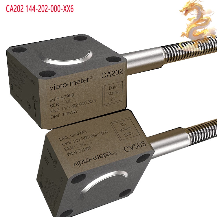
.jpg)
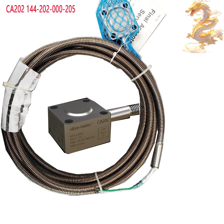
All products on this website are specialized items; market prices are subject to frequent fluctuations.
Please rely on the quotes provided by our customer service team. As these are new products, the prices displayed may not be final.
Before placing an order, please confirm the specific model, product details, and pricing with our customer service representatives.
I. Operating Principle
The 143-232-000-231 piezoelectric dynamic pressure sensor operates based on the direct piezoelectric effect of quartz crystals. When pressure is applied to the sensing diaphragm, the load is transmitted to an internal quartz piezoelectric element. Mechanical deformation of the crystal induces polarization, generating an electrical charge on the electrode surfaces that is directly proportional to the change in pressure; the faster the pressure changes, the more rapid the charge output response. This model features an integrated acceleration compensation component, which cancels out measurement interference caused by vibrations of the equipment itself. The sensor produces a high-impedance charge signal that cannot be acquired directly; it must be connected to a compatible charge amplifier or a dedicated signal conditioning module. This converts the minute charge into a standard voltage signal, which can then be fed into high-speed data acquisition equipment for waveform recording and analysis. Because the charge generated by the quartz piezoelectric element gradually leaks away under constant pressure, this sensor is suitable only for measuring alternating, pulsating, or transient dynamic pressures; it is not designed for long-term static (constant) pressure monitoring.
II. Product Advantages
Integrated acceleration compensation effectively suppresses interference from equipment vibration, ensuring stable measurements even in rotating machinery environments characterized by intense vibration—a core advantage of this series.
Wide frequency response, spanning from low-frequency combustion oscillations to high-frequency pressure pulsations, allows for the complete capture of continuous waveforms related to combustion instability and pressure oscillations.
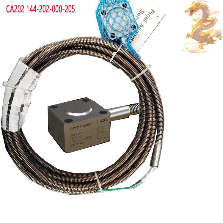
Designed for high-temperature resilience, the sensor is well-suited for the demanding, high-temperature conditions found in the combustion chambers of internal combustion engines and gas turbines, enabling long-term operation within high-temperature environments. Utilizes a quartz piezoelectric crystal, offering stable sensitivity, excellent control over temperature drift, high repeatability, and consistent data for long-term monitoring.
Features a robust, stainless-steel housing designed for high impact and fatigue resistance; suitable for continuous online monitoring rather than just one-off testing.
Provides excellent linearity in charge output, enabling the precise detection of low-amplitude pressure fluctuations and the capture of early-stage combustion instability signals.
Equipped with a standardized connector interface, ensuring strong compatibility with original Vibro-Meter signal conditioners as well as mainstream charge-amplifier-based data acquisition systems.
Compact design with a threaded mounting structure allows for direct installation into pre-existing pressure-measurement ports on cylinders, combustion chambers, or gas turbine casings, requiring minimal modification effort.
III. Applicable Industries and Functions
Gas Turbine and Turbomachinery Industry: Monitors combustion oscillations and thermoacoustic pressure pulsations within combustion chambers. Identifies risks such as combustion instability, flashback, and oscillations, providing essential data for combustion control, structural optimization of combustion chambers, and early fault warning—thereby ensuring the safe, stable, and long-term operation of gas turbine units.
Internal Combustion Engine and Power Machinery Industry: Monitors dynamic in-cylinder pressure for diesel and natural gas engines. Analyzes combustion cycle variability, engine knocking, and combustion oscillations to support engine calibration, optimization of combustion strategies, efficiency improvements, and knock protection.
Aero-Propulsion and Gas-Powered Systems R&D: Used for dynamic combustion testing in aero-combustors and small-scale power units; evaluates combustion stability and supports the research, development, and validation of propulsion systems.
Petrochemical and Industrial Combustion Equipment: Monitors pressure pulsations in industrial burners and heating furnaces; helps predict risks related to combustion resonance, noise, and equipment fatigue damage. Combustion dynamics testing in research institutes: Fundamental combustion research, premixed combustion, and oscillatory combustion testing—capturing parameters such as pressure pulsation frequency spectra, amplitudes, and phases.
Note: This model is not an impact-type piezoelectric sensor designed for applications like explosion/shock testing, water hammer analysis, or Hopkinson pressure bar testing. For such scenarios, please select specialized impact-testing piezoelectric sensors.
IV. Operating Procedures
Pre-installation Inspection: Verify the model number (143-232-000-231). Inspect the housing and connector for any dents or damage, and ensure the pressure-sensing surface is clean and free of burrs. Confirm that the measurement range and maximum operating temperature meet the requirements of the specific application, and verify the factory-calibrated sensitivity of the sensor.

Installation Preparation: Clean the threaded hole and sealing surface of the pressure-measurement port on the equipment to ensure a flat, clean interface. Screw in the sensor using the specified torque; do not overtighten, as excessive force can alter the preload on the internal quartz crystal or cause deformation of the diaphragm. Ensure a proper seal to prevent leakage of high-temperature media.
Cable and Signal Chain Connection: Use the designated low-noise, shielded cable. Connect one end to the sensor and the other to a compatible charge amplifier or signal conditioner. Connect the output of the conditioner to a high-speed data acquisition system. Ensure all connectors are securely tightened, and ground the shielding layer at a single point as required.
Power-up, Warm-up, and Parameter Configuration: Power on the charge amplifier and data acquisition equipment, allowing sufficient time for warm-up. Input the sensor’s factory-calibrated sensitivity, configure the sampling rate, bandwidth, and trigger parameters, and perform a zero-offset adjustment.
Data Acquisition: Initiate the equipment operation or combustion process. Continuously acquire dynamic pressure pulsation signals, monitoring pressure waveforms and frequency spectra in real time. Record data continuously in "online monitoring" mode, or save specific test files as needed during experimental runs. Dismantling after testing: Once the unit has cooled down and the pressure has been released, shut down the data acquisition equipment and signal conditioners in sequence. Disconnect the signal cables and use appropriate tools to remove the sensor. Clean the pressure-bearing surface and threads, then store the sensor in a dry, dust-proof container.
V. Precautions for Use
This sensor is of the dynamic charge-output type and is not suitable for measuring static or constant pressure over extended periods; under constant pressure, the charge will continuously leak, leading to reading drift and distortion.
Strictly control the temperature of the medium; it must not exceed the sensor's rated maximum operating temperature. Exceeding this limit can cause permanent failure of the piezoelectric element and sensitivity drift.
The sensor must be used with a compatible charge amplifier or signal conditioner. The sensitivity parameter settings must match those specified in the factory calibration certificate; incorrect parameters will directly lead to errors in amplitude calculation.
Use low-noise, shielded cables specifically designed for piezoelectric sensors. Keep cables as short as possible and away from strong electromagnetic interference sources, such as variable-frequency drives (VFDs) or high-power motors. Avoid repeated bending or dragging of the cables to prevent degradation of insulation and subsequent charge leakage.
Follow the installation torque specifications strictly. Excessive torque can damage internal sensitive components, while insufficient torque may result in seal leakage or zero-point drift under vibration.
Ensure the pressure-bearing medium is compatible with the sensor housing material. If the medium contains hard particles, assess the risk of erosion and wear; implement protective measures if necessary to prevent damage to the diaphragm.
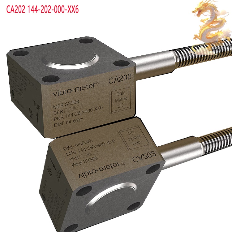
The sensor contains a precision quartz piezoelectric element; do not drop it or subject the pressure-bearing surface to impacts. Store the sensor in a dry environment free from corrosive gases, and ensure the connector is protected against dust.
Periodic calibration: Send the sensor for calibration according to the established metrological cycle to verify its sensitivity and frequency response. For long-term in-situ use, regularly inspect connectors and cables for signs of aging. Although equipped with built-in acceleration compensation, one should still avoid severe impacts that far exceed the design limits, as excessive force can still cause damage to the internal structure.
Recommended products:
143-232-000-211
143-232-000-112
143-232-000-111
143-231-000-162
143-231-000-161
143-231-000-152
143-231-000-151
143-231-000-142
143-231-000-141
143-231-000-132
143-231-000-131
143-231-000-122
143-231-000-021
CP21X 143-216-000-151
CP21X 143-216-000-141
CP21X 143-216-000-131
CP21X 143-216-000-121
More......
PRODUCT TAGS
RELATED PRODUCTS
PLC Dragon Automation
Address: Wanda Plaza, Chengdu, Sichuan Province
Google email: wkcarshop666888@gmail.com
Industrial Control Sales Consultant: Amelia
Whatsapp: +86 18030295882