Kongsberg TRX32 Transceiver Circuit Board Module-TRX32
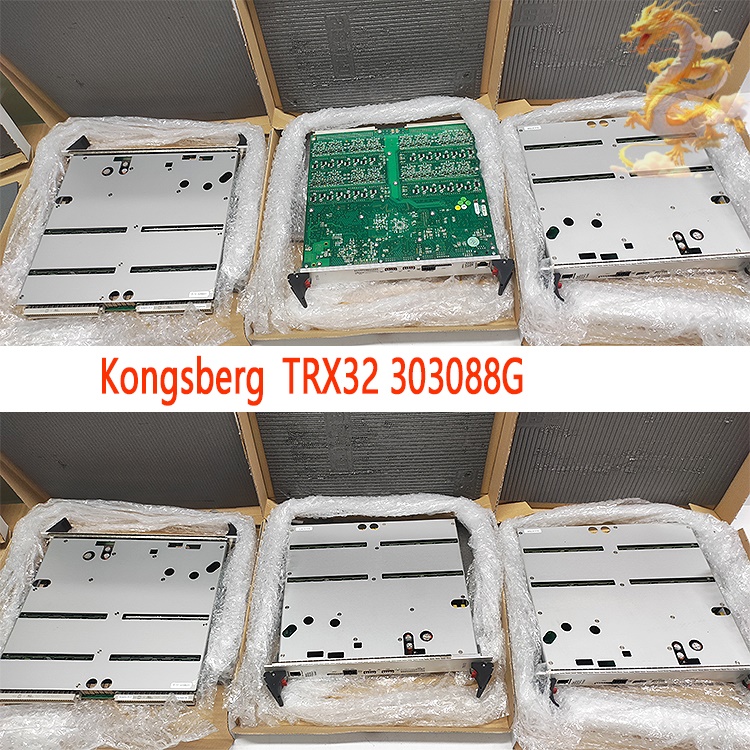
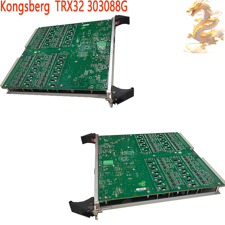
This is a 32-channel, multi-frequency acoustic transceiver circuit board for the Kongsberg Maritime HiPAP series of high-precision underwater acoustic positioning systems. Classified as a Line Replaceable Unit (LRU), it integrates transmit driving, receive pre-amplification, signal filtering, digitization, and DSP signal processing functions, serving as the core circuit board for the HiPAP 101/351/451/501 acoustic positioning main cabinet (X81 transceiver unit). The board features a marine-grade conformal-coated PCB with a reinforced metal shielding cover, making it suitable for the high-vibration and salt-mist environments found on vessels and offshore platforms. Up to eight boards can be installed in a single cabinet to expand acoustic channel capacity; the board provides raw acoustic signal data for underwater target direction-finding and ranging, which is then transmitted to the HiPAP main control unit for position calculation and support of the vessel's Dynamic Positioning (DP) system.

.jpg)
.jpg)
.jpg)
All products on this site are specialized items subject to fluctuating market prices;
Actual pricing is based on quotes provided by customer service. As these are specialized products, listed prices may not reflect current rates;
Please confirm the model, product specifications, and pricing with customer service before placing an order;
Please contact customer service for details regarding available units.
TRX32 Alternative Names:
TRX32 Ultrasonic Transceiver Module
TRX32 Multi-frequency Acoustic Transceiver Circuit Board
TRX32 Integrated Transmit Drive Unit
The Kongsberg TRX32 is a 32-channel, multi-frequency acoustic transceiver circuit board designed for the Kongsberg Maritime HiPAP series of high-precision underwater acoustic positioning systems. Classified as a Line Replaceable Unit (LRU), it integrates transmit driving, receive pre-amplification, signal filtering, digitization, and DSP signal processing functions. It serves as the core circuit board for the X81 transceiver unit within the HiPAP 101/351/451/501 acoustic positioning main cabinets. The board features a marine-grade conformal-coated PCB and a reinforced metal shielding cover, making it suitable for the high-vibration and salt-spray environments found on vessels and offshore platforms. Up to eight TRX32 boards can be installed in a single cabinet to expand acoustic channel capacity. It provides raw acoustic signal data for underwater target direction-finding and ranging; this data is transmitted to the HiPAP main control unit for position calculation, supporting the vessel's Dynamic Positioning (DP) system.
I. Operating Principle
The TRX32 board operates through the coordination of five major modules: the transmit link, the receive link, the DSP digital processing unit, the power and synchronization unit, and the Ethernet communication unit. Transmit Link: Under the control of the HiPAP master unit, positioning commands and encoded pulse sequences are sent to the TRX32. An onboard DSP generates multi-frequency acoustic excitation signals, which drive the underwater transducer array elements via a power amplification circuit, converting electrical signals into underwater acoustic pulses for transmission. Each board independently manages 32 transmit channels and supports multi-frequency switching to match the operating frequencies of underwater transponders. An onboard high-capacity energy storage capacitor array ensures the supply of peak power during the instant of pulse transmission.
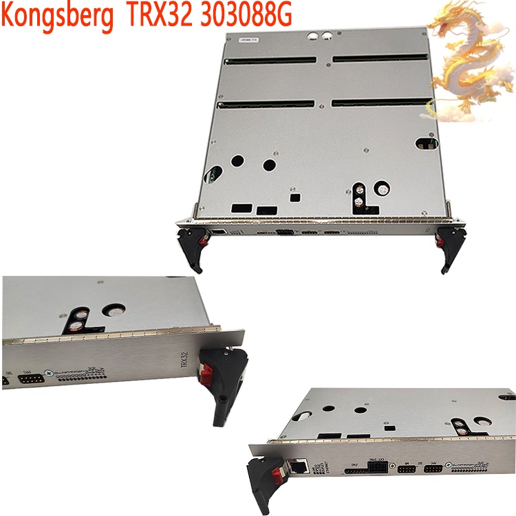
Receive Link: Acoustic echoes from seafloor transponders are converted by the transducer into weak electrical signals and fed into the TRX32. These signals undergo low-noise pre-amplification and band-pass filtering to eliminate marine environmental noise and electromechanical interference from the vessel, followed by digitization via high-speed ADCs. The 32 receive channels acquire echo waveforms in parallel, preserving phase and amplitude information to provide raw sampled data for beamforming and time-delay measurements. The board features dual-fuse protection: F1 (12V/4A) and F2 (6V/4A) safeguard the power supply circuits.
DSP Signal Processing Unit: This unit performs digital filtering, pulse correlation decoding, and signal threshold detection on the digitized echoes. It calculates the acoustic round-trip time (TOA) and signal arrival phase difference, completing preliminary processing of target time delay and bearing to reduce the computational load on the master control computer. A 20MHz master clock and external trigger synchronization signals ensure strict timing synchronization across multiple TRX32 boards and transducer arrays.
Communication Unit: Pre-processed acoustic measurement data packets are uploaded in real-time to the HiPAP master control unit via the Ethernet interface on the front panel. Simultaneously, the unit receives parameter configurations, transmission triggers, and channel start/stop commands from the master unit. The front panel includes LINK/ACT and I/O status indicators for hardware diagnostics, along with reserved interfaces—a P4 external synchronization interface and P5/P7 debugging serial ports—for engineering debugging. Address Configuration Unit: DIP switches SW1 and SW2 on the board are used to set the hardware ID. In scenarios where multiple TRX32 units are connected in parallel within the same cabinet, these switches distinguish the channel addresses of different boards to prevent communication conflicts.
.jpg)
Operational Closed-Loop: Host computer issues positioning commands → TRX32 drives the transducer to emit acoustic waves → Seabed transponder returns an echo → TRX32 acquires, amplifies, and digitizes the echo signal → DSP performs preprocessing → Raw ranging and bearing data are uploaded via Ethernet → HiPAP master controller calculates the 3D coordinates of the underwater target and outputs the final data to the vessel's K-Pos dynamic positioning system.
II. Application Scenarios
The TRX32 is designed exclusively for use with the Kongsberg HiPAP high-precision underwater acoustic positioning system, with applications focused on offshore engineering and vessel dynamic positioning (DP):
ROV/AUV Underwater Tracking and Positioning: Offshore construction vessels and diving support vessels (DSVs) utilize the HiPAP+TRX32 system to track the real-time position of underwater robots, ensuring the safety and accuracy of underwater pipeline laying, wellhead operations, and subsea maintenance tasks.
Seabed Transponder Array Positioning: Drilling platforms and Floating Production, Storage, and Offloading (FPSO) units use this system to read seabed transponder arrays, enabling absolute position monitoring of the platform and serving as a core position reference source for dynamic positioning.
Towed Body and Underwater Detector Trajectory Monitoring: Marine scientific research vessels and survey ships track the underwater position of towed detection equipment for seabed topographic mapping and geophysical survey operations.
Offshore Equipment Installation: During the lifting and positioning of structures such as jacket foundations, subsea bases, and modules, the system relies on HiPAP acoustic positioning; the TRX32 acquires acoustic signals to achieve centimeter-level underwater relative positioning.
Vessel Dynamic Positioning Redundant Reference: Acting as one of the position sensors for the DP system, it ensures the positioning safety of the platform or vessel via underwater acoustic positioning in the event of GPS failure. III. Operating Procedures
Prerequisites: Operators must be familiar with the HiPAP system manual and hold the necessary qualifications for operating marine/offshore equipment. Hot-swapping is permitted only if the system design supports the LRU (Line Replaceable Unit) online replacement mode; for routine maintenance, powering down the system is recommended.
(i) Installation Procedure
Power-off Confirmation: Power down the HiPAP transceiver unit (X81 cabinet), lock the power switch, and implement Lockout/Tagout (LOTO) procedures.
Card Inspection: Remove the TRX32 card and visually inspect it: ensure there is no PCB corrosion or capacitor bulging, the shielding cover is intact, and the edge connectors show no signs of oxidation. Verify that the spare part model is TRX32.
DIP Switch Configuration: Set the SW1/SW2 DIP switches based on the cabinet slot number to configure the card's hardware address, ensuring it matches the configuration table in the host system.
.jpg)
Rack Insertion: Smoothly insert the card along the chassis guide rails, aligning it with the Euro-style backplane connector. Press down the upper and lower card ejectors to lock the card in place, ensuring full engagement with the backplane connector.
External Cabling: Connect the front-panel Ethernet and external synchronization (P4) cables; verify that the cables are securely fastened.
Power-up and Initialization: Remove LOTO measures and power up the cabinet. Observe the front-panel power and network port indicators: the power LED should remain steadily lit, the network LINK LED should be steadily on, and the ACT LED should flash according to data activity.
Host System Recognition: Log in to the HiPAP control software and scan for hardware to confirm the system recognizes the TRX32 card and that there are no hardware alarms regarding channel status. Load the transducer channel parameters and perform a channel self-test.
(ii) Routine Operation
During normal system operation, there is no need to interact directly with the card hardware. Monitor the TRX32 card status solely via the host monitoring interface, checking parameters such as power supply status, signal-to-noise ratio (SNR) for the 32 channels, temperature, and communication link status. Channel activation/deactivation, transmit power, operating frequency, and signal thresholds are all configured via the HiPAP software and sent to the TRX32; direct modification of the board's hardware circuitry is not permitted.
Perform periodic system acoustic self-tests and loop tests on every transmit/receive channel to detect any signal attenuation or open circuits.
(III) Removal and Replacement Procedure
If hot-swapping is supported: Set the TRX32 in the specific slot to "offline" via the host software, disable all transmit channels on the board, and stop acoustic pulse output. If hot-swapping is not supported, power down the entire unit and apply Lockout/Tagout (LOTO) procedures.
Disconnect the Ethernet and synchronization signal cables from the front panel.
Press the red locking button on the ejector mechanism, operate the upper and lower ejector levers (moving them up and down), disengage the board from the backplane connector, and slowly slide it out along the guide rails.
.jpg)
Reinstall the new board following the installation procedure described above; complete address configuration and power-on self-tests, then perform channel calibration.
After replacement, recalibrate channel gain in the HiPAP software and conduct acoustic positioning tests; verify that positioning accuracy meets specifications before returning the unit to service.
IV. Precautions
1. Electrostatic Protection (Critical Importance)
The TRX32 board contains high-speed DSPs, ADCs, and other precision
semiconductor components that are highly susceptible to damage from
electrostatic discharge (ESD). Personnel must wear certified anti-static wrist
straps and anti-static clothing throughout the removal and installation process.
Boards must be stored and transported in anti-static bags; touching the
component side or gold fingers of the board with bare hands is strictly
prohibited. The risk of static electricity is higher in the dry environments
often found on ships; opening the shielding cover without proper ESD protection
is prohibited.
2. Power Supply and Fuse Protection
Verify the cabinet's supply voltage before powering on; inputting voltage exceeding the rated limit is strictly prohibited. If fuses F1 and F2 on the board blow, do not simply replace them and power on again; you must first troubleshoot and resolve any downstream short circuits or transducer cable leakage faults before installing fuses of the same specification.
The board's energy-storage capacitors retain residual high voltage; after powering down, allow sufficient time for discharge before opening the shielding cover to prevent electric shock.
3. Environmental and Mechanical Requirements
This board is designed for installation inside a cabinet and must not be exposed to open-deck environments. Ensure the cabinet remains ventilated and the internal temperature is controlled to avoid high heat and condensation.
Shipboard vibration and shock can cause connectors to loosen; during inspections, verify that the board ejector mechanism is securely locked. Do not remove the shielding cover arbitrarily, as it provides both electromagnetic shielding and mechanical reinforcement; removal introduces electromagnetic interference, which degrades the signal-to-noise ratio of the receiving channels.
Do not scratch the board's protective coating; damage to the coating accelerates salt-spray corrosion, which can lead to channel drift faults during long-term operation.
4. System Timing and Configuration Constraints
Within a single X81 cabinet, DIP switch addresses for multiple TRX32 boards must not overlap; address conflicts will directly result in communication anomalies and positioning failure.
Do not arbitrarily modify the board's hardware DIP switch settings. If an address is changed, the hardware configuration must be updated synchronously on the host computer, and the corresponding board must be rebooted to register the change.
Faults in the 20MHz master clock or external synchronization cables will
cause timing desynchronization across multiple boards, leading to beamforming
failure and bearing measurement errors; do not arbitrarily disconnect or
reconnect synchronization signal cables.
5. Operational Safety Restrictions
Acoustic transmission involves significant power output; do not activate transmission channels blindly while divers are working underwater, as acoustic pulses can cause injury to divers.
If channel alarms, board overheating, or unusual odors occur, immediately disable the transmission channel via the host software. Cut power to the cabinet if necessary; do not continue operation with a faulty unit, as this could exacerbate the failure or even damage the transducer array.
6. Maintenance and Spare Parts
The TRX32 is an LRU (Line Replaceable Unit); board-level repairs are not permitted in the field. Replace the entire board in the event of component failure, and send the faulty board to Kongsberg or an authorized service provider for repair.
Store spare parts in a dry environment, avoiding high temperatures and humidity. Conduct periodic visual inspections and perform a preliminary power-on test before using a spare part.
7. Commissioning and Calibration
Channel gain calibration must be performed after replacing a board. Imbalance in single-channel gain can lead to beam distortion and reduced positioning accuracy. Calibration requires the dedicated HiPAP calibration tools; do not skip calibration and proceed directly to using the unit in the DP system.
V. Quick Fault Diagnosis Reference
No power indicator light upon power-up: Check the cabinet power supply and the board's fuse.
Power normal, but network LINK light off: Check the network cable, backplane connector contact, and board address configuration.
Low channel signal-to-noise ratio: Check the shielding cover and transducer cables, investigate electromagnetic interference, and verify if the receiver pre-amplifier circuit is damaged.
Significant positioning/bearing deviation: Prioritize checking the synchronization clock across multiple TRX32 boards and verifying whether the channel gain calibration remains valid.
Recommended related products:
PPD113-B03-23-111615
PPD113B01-10-150000
PPD113B03-26-100110
PPD517A3011 3BHE041576R3011
PPD517 3BHE041576R3011
PDD200A101 3BHE019633R0101
PDD200A101 3BHE019634P201ANEDA
PDD205A1121 3BHE025335R1121
PDD205A1121 3BHE025335R1121
PDD500A101 3BHE037649R0101
3BHE039724R0E41 PPD513
More......
PRODUCT TAGS
RELATED PRODUCTS
.jpg)
PLC Dragon Automation
Address: Wanda Plaza, Chengdu, Sichuan Province
Google email: wkcarshop666888@gmail.com
Industrial Control Sales Consultant: Amelia
Whatsapp: +86 18030295882
12A3256BC9DA41BAB264DB676273DA32.png)


3BE7E049824E4F11BE61AD65D86DFEBD.png)