
MNS iS Motor Control Center Interface Manual MLink HW 1TGE120021 System Release V7.0
Date: Jun 11, 2025Views:
Related Documentation
MNS iS
1TGC910211 M0201 MNS iS Interface Manual MLink, Release 7.0
1TGC910111 M0201 MNS iS MLink Upgrade Kit Manual
1TGC910221 M0201 MNS iS Interface Manual Web Interface, Release 7.0
1TGC910241 M0201 MNS iS Interface Manual Profibus, Release 7.0
1TGC910251 M0201 MNS iS Interface Manual Modbus, Release 7.0
1TGC910291 M0201 MNS iS Interface Manual PROFINET IO, Release 7.0
1TGC910281 M0201 MNS iS MControl Interface Manual Profibus Direct, Release 7.0
1TGC910261 M0201 MNS iS Interface Manual Redundancy, Release 7.0
1TGC910271 M0201 MNS iS MConnect Interface Manual, Release 7.0
1TGC910001 B0204 MNS iS System Guide
1TGC910201 M0201 MNS iS Quick Guide Installation and System Setup, Release 7.0
1TGC910090 M0201 MNavigate Help file V7.0
1TGC910018 M0208 MNS iS ATEX – Enhancements for Safety
Related System Version
The content of this document is related to MNS iS System Release 7.0.
The described functions are designed but may not be fully implemented in all details. Please refer to the current system guides and release notes regarding possible restrictions.
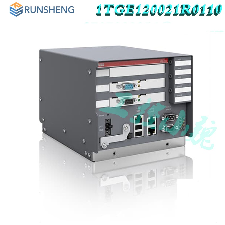
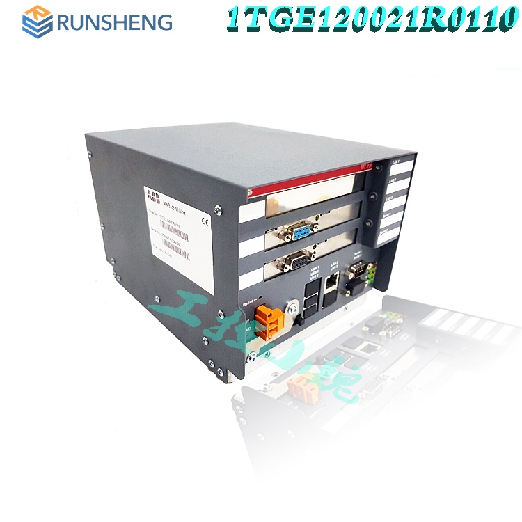
The system interface MLink is an industrial PC equipped with interface cards and ports required for communication internally to MControl and externally to process control systems.
One MLink can communicate internally with up to 60 MControl. If more than 60 MControl are required, then additional MLinks have to be used.
Hardware Types and Technical Data
The configuration of MLink depends on the selected communication protocol to the DCS. Following communication interface protocols are available:
· PROFIBUS DP (-V0) and PROFIBUS DP-V1
· MODBUS RTU / TCP
· PROFINET IO
System functions such as MLink web interface (MView), OPC connectivity and time stamp are possible with all MLink types.
For communication to MControl a dedicated interface plug (switchgear bus connector) has to be used dependent on system configuration (redundant, non redundant system).
Electrical Data
Power Supply 24V DC (19 – 31V DC)
Power Consumption Typical 800mA, Maximum 1000mA
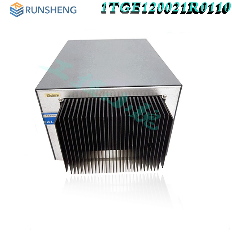
Mechanical Data
Weight 2.5 kg
Dimensions H x W x D 140 x 160 x 165 mm
Environmental Data
Storage Temperature -20°C to +70°C
Operating Temperature 0°C to +55°C
Degree of Protection IP 51
MTBF (Mean Time Between Failures) 46 years @ 40°C
Swg Bus
Switchgear Bus Interface (female blue plug)
Swg Bus – upper LED, yellow Switchgear Bus Rx Indication
Swg Bus – lower LED, yellow Switchgear Bus Tx Indication
Profibus
PROFIBUS DP Slave Interface (female black plug)
Profibus – upper LED, yellow Profibus Communication running
Profibus – lower LED, green Profibus READY for communication
Power Supply
Button Reset Reset button (Restart of MLink)
24V Power Supply +24VDC
GND Power Supply 0V
CF card
CF card CF card is protected against unintentional removal after closing the flap and connecting the power supply (details see page 24)
LAN
LAN 1 LAN1 Interface (Modbus TCP/ Profinet)
LAN 1 – LED left, green Link LAN1 active
LAN 1 – LED right, yellow Communication Ethernet LAN1
LAN 2 LAN2 Interface
LAN 2 – LED left, green Link LAN2 active
LAN 2 – LED right, yellow Communication Ethernet LAN2
LAN 3 Not used
LAN 3 – LEDs Not used
USB 1, 2 Not used
Serial 1 Redundancy Interface (male plug)
Serial 2 Modbus RTU Interface (female plug)
LED indications
LED 1 MLink Run indication (CF card application loaded and running)
LED 2 MLink Fault
LED 3 Application dependent (see section LED indication, page 27)
LED 4 Application dependent (see section LED indication, page 27)
LED 5 Application dependent (see section LED indication, page 27)
LED 6 DCS Communication active (PROFIBUS or Modbus)
LED 7 MLink Power On Indication
LED 8 Application dependent (see section LED indication, page 27) In redundant configurations: MLink primary
Power Supply
The MLink requires 24V DC supply voltage. The connection is on the right side of the device with terminal plugs:
· Terminal 1 connects to +24V DC
· Terminal 2 connects to 0V DC
Software Modules
MLink contains different software modules depending on its initial configuration. The software modules are available on request.
Following software modules are available:
· Web Server
· OPC Server (DA & AE)
· Fieldbus
· Time Synchronization
· Redundant Operation
If a specific module is not available on the MLink, please contact your local ABB LVS Sales organization should this be required.
Web Server
A Web Server can be activated inside MLink. Through network connection web interface information can be displayed on MView or a PC using web browser software. For details about Web Interface see the document:
MNS iS Interface Manual Web Interface.
OPC Server
With MNS iS an OPC Server (DA & AE) is available. The software is typically installed on a server as part of the automation control system. The software installation program is delivered separately. If activated, the MLink functions as a data provider for the MNS iS OPC Server. For details about OPC Server see the document:
MNS iS Interface Manual OPC Server.
Fieldbus
MLink can include Fieldbus communication to DCS. The type of Fieldbus must be selected before ordering the MLink type. The Fieldbus specific information (PROFIBUS, MODBUS etc.) can be found in the following documents:
MNS iS Interface Manual Profibus
MNS iS Interface Manual Modbus
MNS iS Interface Manual Profinet IO
Communication Interface Connection
Switchgear Network (internal)
The internal communication between MLink and MControl is via the switchgear bus. The wiring is located within the MNS iS cubicle. The bus cable is connected to the blue Sub-D 9 terminal located on the front of the MLink at the upper part of the device. The internal communication does not require any configuration.
Switchgear Control Network
MLink can be connected to a standard 10/100 Base-T Ethernet network through LAN2 interface (Switchgear Control Network). Network components are standard (COTS – commercial of the shelf) components. No specific components are required connecting MLink to the network.
Examples of connections are shown in the following figures. Additional MLink and MNS iS tools (Engineering tool MNavigate, web interface, OPC Server, Time Server) are connected to this network (see Figure 2). The cable is CAT5, connector type is standard RJ45 type.
Connection examples of Switchgear Control Network
Option 1
If the MLink is directly connected to MView or a PC with web browser a cross-over network cable is used. On the MLink, the cable has to be connected to the right Ethernet connector (LAN2), on MView the cable has to be connected to the Ethernet connector. The cable type is CAT5 cable.
Option 2
MLink connected to Switchgear Control Network providing facility to connect additional MNS iS MLink and tools (e.g. OPC Server, PC with web browser for monitoring etc.). A network switch has to be installed in the plant. MLink and MView are connected to the switch with standard CAT5 patch cable.
Option 2 allows using fewer number of MView. However, all MLink connected to the same network can display their data on all MView connected to the same network.
Time Synchronization
In the MControl Alarms and Events can be provided with a time stamp. The time and date is received on MControl from MLink via the internal switchgear bus. In order to provide the correct time and date the Time Sync option must be activated in MLink and it may require a time server in the switchgear control network.
The protocol used for time synchronization is the standard network time protocol (NTP).
Option 1
A standard network component is installed which can provide the time signal as NTP Server. Such a NTP Server can be a computer or network server as well as Ethernet switches. As an option, this NTP Server can be equipped with a GPS Receiver to provide accurate time for the location.
Option 2
One MLink in the network is configured to run with its internal real time clock (RTC). In this case the date and time for this MLink must be set through the web interface (see doc. MNS iS Interface Manual Web Interface). This MLink acts as a time server (NTP Server) in the switchgear control network. Other MLinks can request the time information from this MLink to synchronize their internal clock.
Getting Started
Initial Values
MLink requires parameter settings as initial values for network operation. The parameters are required depending on MLink configuration. Additionally parameter for Web Server, OPC Server and Fieldbus are also required (see respective Interface Manuals).
The parameters have to be loaded onto the Compact Flash (CF) card before power up using MNavigate tool. After successful communication between MNavigate and MLink (either direct or via network) the parameters can then be changed from MNavigate through the network.
![]() 1TGC910211M0203 MNSiS Interface Manual MLink_Rel_7.0.pdf
1TGC910211M0203 MNSiS Interface Manual MLink_Rel_7.0.pdf
Related product recommendations:
DEIF 879 3C
DEIF TEMAX-3/B
DEIF OPM-1 1044220080E
IMD 122B DEIF
PCM4-2 DEIF
PCM4-1 DEIF
PCM4-3 DEIF
PCM4-4 DEIF
PCM5-2 DEIF
AGI 315 DEIF
AGC 245 DEIF
AGC 243 DEIF
SG-C4 DEIF
IMD 122C DEIF
More...
RELATED ARTICLE
PLC Dragon Automation
Address: Wanda Plaza, Chengdu, Sichuan Province
Google email: wkcarshop666888@gmail.com
Industrial Control Sales Consultant: Amelia
Whatsapp: +86 18030295882
12A3256BC9DA41BAB264DB676273DA32.png)


3BE7E049824E4F11BE61AD65D86DFEBD.png)