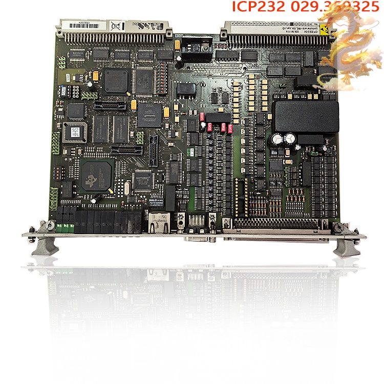
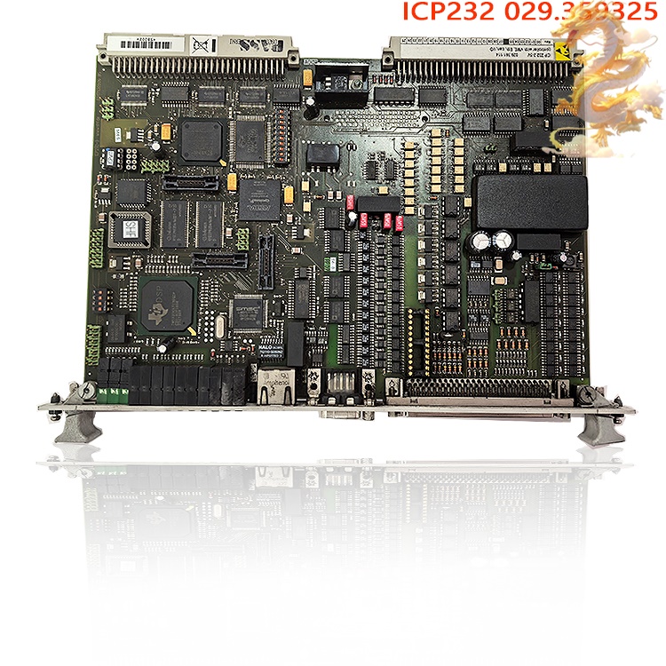
ALSTOM | ICP232.2-5V 029.361114 | Logic Operation Module | ICP232.2-5V 029.361114
It reads analog and digital signals (such as voltage, current, discrete I/O, and encoder feedback) acquired by I/O modules within the rack via the VME backplane bus. A single processor independently executes control algorithms, logic interlocks, and protection functions—such as generator excitation regulation, traction converter PWM calculations, and safety interlock protection—without relying entirely on a host computer for processing. Built around an industrial-grade 32-bit single-core processor with onboard Flash and SDRAM, it integrates multiple interfaces including VME backplane bus, CAN bus, Ethernet, and RS-232; it is a rack-mounted controller card rather than a simple protocol conversion board.
.jpg)
.jpg)
All products on this site are specialized items subject to market price fluctuations.
Please refer to the customer service quote for actual pricing; the listed prices are not final.
Please confirm details—such as model, product specifications, and price—with customer service before placing an order.
Please contact customer service for further discussion.
ICP232.2-5V 029.361114
Alternative Names:
Industrial Logic Processing Module ICP232.2-5V 029.361114
I. ALSTOM ICP232.2-5V 029.361114 Controller Operating Principle
The ALSTOM ICP232.2-5V 029.361114 is a single-processor embedded controller based on the VME bus architecture. It features an industrial-grade 32-bit single-core processor and onboard Flash and SDRAM memory. It integrates multiple interfaces—including VME backplane bus, CAN bus, Ethernet, and RS-232—and is designed as a rack-mount plug-in card rather than a simple protocol conversion board.
Power-on Self-Test (POST) and Firmware Loading: Upon insertion into the VME rack backplane and power-up, the module first performs a hardware self-test covering the processor, memory, communication transceiver chips, power monitoring circuits, and isolation circuits. If the self-test passes, the module loads the embedded firmware and user control program from the onboard Flash memory. If the self-test fails, a fault indicator on the front panel lights up, and a fault code is reported to the system's main management unit via the VME backplane.
Signal Acquisition and Local Logic Processing: The module reads analog and digital signals (voltage, current, discrete I/O, encoder feedback, etc.) acquired by I/O modules within the rack via the VME backplane bus. The single processor independently executes control algorithms, logic interlocks, and protection logic—such as generator excitation regulation, traction converter PWM calculations, and safety interlock protection—without relying entirely on a host computer for processing. Multi-bus Data Exchange and Protocol Forwarding
VME Backplane Bus: Serves as the local high-speed internal bus for exchanging real-time control data with other I/O and communication cards within the rack;
CAN Bus: Used for real-time control communication with field-level devices;
RS-232 Serial Port: Used for local debugging and connecting to serial instruments, HMIs, and O&M terminals;
Ethernet: Used to upload operational data and fault records to the SCADA supervisory system.
Fault Diagnosis and Status Reporting: The processor continuously monitors supply voltage, card temperature, bit error rates of communication links, and I/O circuit status. Upon detecting bus interruptions, out-of-limit signals, or hardware anomalies, it immediately triggers protective actions and caches fault event logs. These logs are uploaded to the system monitoring unit via the backplane or network, enabling fault traceability.
Core Positioning: The ICP232.2-5V 029.361114 performs the dual roles of field real-time controller and multi-bus protocol gateway; it executes closed-loop control algorithms while bridging data across different buses, acting as the local control node for the entire distributed control system.
II.
ALSTOM ICP232.2-5V 029.361114 Usage Instructions (Rack-mount VME Plug-in
Module)
1. Preparation and Model Verification
Verify Part Number: ICP232.2-5V 029.361114 ; confirm firmware version compatibility with the existing system;
Prepare Accessories: ALSTOM standard VME rack, dedicated backplane, 24VDC rack power supply, RS-232 debugging cable, host configuration software, and anti-static wrist strap;
Environmental Check: Ensure the cabinet is free of dust accumulation and corrosive gases, and is located away from strong electromagnetic interference sources such as variable frequency drives (VFDs) and high-power contactors.
.jpg)
2. Hardware Installation (VME Rack Insertion/Removal)
⚠️ Power must be completely disconnected from the unit before performing this operation.
Wear an anti-static wrist strap to discharge static electricity from your body;
Remove the blank panel from the rack slot, align the ICP232.2-5V 029.361114 module with the guide rails, and slide it in steadily;
Once the module is fully inserted, tighten the mounting screws at the top and bottom of the front panel to ensure full contact with the backplane connector;
Verify that other boards in the rack are correctly installed and that backplane connections are secure.
3. External Wiring
RS232 Debug Port: DB9 interface; use a shielded serial cable to connect to a PC debug terminal;
CAN Bus: Shielded twisted-pair cable; install 120Ω terminating resistors at both ends of the bus; ensure differential signal lines are not reversed;
Ethernet: Industrial shielded Ethernet cable; connect to the system switch;
Route
external signal cables and power cables separately to minimize EMI
interference.
4. Power-up, Parameter Configuration, and
Program Download
Verify the rack power supply connections and power up the unit; wait for the board's self-test to complete. A steady power indicator and an extinguished fault indicator signify a successful self-test.
Connect the PC to the ICP232.2-5V 029.361114 via the RS232 debug port and launch the ALSTOM configuration software.
Configure parameters: RS232 baud rate, CAN bus speed, Ethernet IP address, I/O mapping, interlocking logic, and protection thresholds.
Download the control program to the onboard Flash memory and save the parameters to ensure data retention after power-off.
Restart the module to load the new configuration; observe the communication indicators to confirm successful handshaking across VME, CAN, and Ethernet links.
5. No-load Test Run and On-site Integrated Commissioning
Conduct no-load testing to verify that acquired signals and output commands match expectations; simulate fault signals to validate interlocking protection, fault alarms, and log recording functions. Once no-load verification is successful, connect field sensors and actuators, proceed to system-wide integrated commissioning, and commence formal operation.
III.
Precautions for Using ALSTOM ICP232.2-5V 029.361114
Electrical Safety
Hot-swapping VME boards while powered on is strictly prohibited; doing so can cause immediate damage to the backplane bus, board processor, and interface chips.
The rack must be powered by a stable 24VDC industrial power supply equipped with surge and overcurrent protection; voltage fluctuations exceeding specified limits may cause module restarts or hardware burnout.
Communication interfaces feature isolation circuitry; unauthorized removal of isolation components or modification of hardware circuits is prohibited.
Shielded cables must be used for CAN and RS232 connections, with the shield grounded at one end only to prevent ground loop interference. Environmental Conditions
Operating temperature: -20°C to +70°C; storage temperature: -40°C to +85°C;
Relative humidity: 5% to 95% (non-condensing); long-term operation in environments with condensation, salt spray, or corrosive gases is prohibited;
Ensure the cabinet is well-ventilated and leave space above the module for heat dissipation; do not place the module in direct contact with heat-generating power boards.
Operation, Maintenance, and Troubleshooting
Inspection: Regularly check panel indicator lights, mounting screws, and terminal blocks; use a dry, anti-static brush to remove surface dust from boards; do not wipe circuit boards directly with alcohol;
.jpg)
If a fault indicator lights up, prioritize checking the rack power supply, backplane connections, and communication lines; fault logs can be retrieved via the debug port;
The board is a precision component; it contains no user-serviceable parts. Do not attempt to disassemble or repair hardware damage yourself; return the unit to the factory or an authorized service provider for repair;
Firmware upgrade: Back up existing programs and parameters before upgrading; do not cut power during the upgrade process, as power loss can damage the firmware and render the module inoperable ("brick" it).
Warehouse Spare Parts Management
Store spare ICP232.2-5V 029.361114 modules in anti-static bags in a dry, dark environment; before installation, power up and test the module on a test rack to confirm it is fully functional before replacing the module currently in use on-site.
IV.
ALSTOM ICP232.2-5V 029.361114 Applicable Industries and Use Cases
Power Generation Industry (Primary Application): Control systems for gas turbines and hydro-generator units; control of power plant auxiliary equipment; substation automation systems. The ICP232.2-5V 029.361114 acquires signals for generator unit voltage, current, and rotational speed, while executing excitation control, overspeed protection, and unit interlocking. It also uploads operational data to SCADA monitoring platforms, serving as the core controller for legacy ALSTOM generator unit DCS (Distributed Control Systems).
Rail Transit Industry: Train traction converter control systems and onboard automation control units. These handle traction power control, converter PWM algorithms, onboard equipment status acquisition, and safety interlocking protection, and are compatible with control cabinets for locomotives and urban rail vehicles.
Industrial Process Automation: Distributed control systems and drive control units for large-scale plants. Used for the closed-loop control of equipment such as pumps, fans, and compressors, these units act as local control nodes, connecting sensors and actuators to supervisory monitoring systems.
Marine Automation (Marine Power Control Systems): Monitoring for ship generator sets and propulsion auxiliary machinery. Capable of performing real-time control and data acquisition for power equipment in harsh marine environments characterized by strong vibration, salt spray, and electromagnetic interference.
V.
ALSTOM ICP232.2-5V 029.361114 Core Advantages
Integrated VME Multi-bus Architecture with High Integration: A single processor integrates VME backplane, CAN, RS232, and Ethernet interfaces. A single module simultaneously handles local control and multi-protocol gateway functions, reducing the number of cards in the rack and simplifying system architecture—making it ideal for retrofitting legacy ALSTOM/GE VME-based systems.
Industrial-Grade High Reliability for Safety-Critical Scenarios: Designed to meet rigorous standards in the energy and rail transit sectors, the unit has undergone testing for vibration, shock, and electromagnetic compatibility (EMC). It features board-level power monitoring and a hardware watchdog timer that automatically resets the system in the event of a program crash, ensuring reliability in critical control applications—such as power plants and train traction systems—where loss of control is unacceptable. Independent Real-Time Processing (No Host PC Dependency): The onboard processor independently executes control algorithms and interlocking logic. Even if the host SCADA network connection is lost, local protection and closed-loop control functions continue to operate, thereby enhancing the overall system's availability and safety.
Multi-Protocol Compatibility (Ideal for Legacy System Retrofitting): It natively supports the ALSTOM VME backplane protocol and is compatible with CAN bus, RS232 serial ports, and Ethernet. Widely used in existing ALSTOM generator sets and traction equipment, this module is a popular replacement part in the global industrial control market; it integrates seamlessly into legacy system upgrades and component replacements without requiring extensive hardware modifications.
Comprehensive Built-in Self-Diagnostics and Fault Logging: The module monitors the status of the board itself and its I/O in real-time, automatically saving fault logs. Maintenance personnel can access historical fault data via the debug port, significantly reducing troubleshooting time and minimizing losses associated with equipment downtime.
Modular Rack Design (Easy Maintenance and Replacement): Featuring a standard VME plug-in card design, the module allows for direct replacement with an identical unit in the event of a failure. The replacement process is streamlined to minimize on-site downtime, making it ideal for applications requiring rapid repair, such as power plants and rail transportation systems.
VI.Related
product examples
ICP232-8DI/8DO: 8 digital inputs + 8 relay outputs, suitable for small and medium-sized control scenarios.
ICP232-16DI/16DO: 16 digital inputs + 16 transistor outputs, supports high-speed pulse control.
ICP232-ETH: Integrated Ethernet interface, supports remote programming and diagnosis.
Related
product recommendations:
MVR1600-4601
MVR1600-4601-A
IS400WNPSH1A
IS400WNPSH1ACB
IS40yTVBAH2B
IS410JPDHG1A
IS400JPDHG1ABB
IS400SRLYS2ABB
IS400STAIS2AED
IS400STAIS2AED
IS400SRLYS2ABB
IS400STCIS2AFF
IS400STCIS2AFF
more......
PRODUCT TAGS
RELATED PRODUCTS
PLC Dragon Automation
Address: Wanda Plaza, Chengdu, Sichuan Province
Google email: wkcarshop666888@gmail.com
Industrial Control Sales Consultant: Amelia
Whatsapp: +86 18030295882
12A3256BC9DA41BAB264DB676273DA32.png)


3BE7E049824E4F11BE61AD65D86DFEBD.png)


.jpg)