
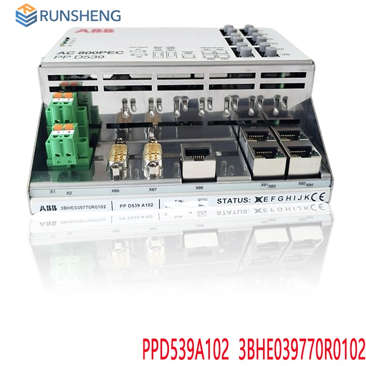
How to program the ABB PPD539A102 3BHE039770R0102 AC 800PEC controller?
Date: Nov 08, 2025Views:
Hardware Configuration and Physical Connections
Controller Installation: Install the CPU module (e.g., PM865), I/O modules, and communication modules (e.g., ProfiBus card) onto a standard DIN rail, ensuring alignment and locking. For example, the CPU module of the AC 800PEC needs to be inserted into the backplane (BP) and connected to the I/O modules or drive equipment via a fiber optic interface (e.g., channels 01-06 of OM1).
I/O Module Expansion: Configure S800/S900 series I/O modules (e.g., digital input PFSA146, analog output PFEA111) according to control requirements, connecting them to the controller via the CEX bus or AnyIO interface to achieve signal acquisition and actuator driving.
Communication Link Setup: Configure dual Ethernet ports to connect to the factory network, supporting OPC UA and MMS protocols; extend the DDCS protocol via the RPBA-01 adapter to adapt to ABB drive equipment.
Wiring and Communication: Configure bus parameters (e.g., baud rate, slave address), and use the ProfiBus configuration tool to create I/O mappings. For example, create a new configuration using the SST ProfiBus tool, set the master/slave station numbers, assign I/O addresses, and connect the ProfiBus cable (terminating resistor configuration required).
Power Supply and Status Monitoring: Before powering on, ensure the power supply is stable and observe the CPU indicator lights (e.g., F fault light, R running light, T communication light), ensuring all links are normal (e.g., 1Hz flashing indicates normal communication).
Software Tools and Development Environment
Programming Tools: Use ABB Control Builder M or Compact Control Builder, supporting IEC 61131-3 standard languages (LD ladder diagram, FBD function block diagram, ST structured text, SFC sequential function chart). Integrate MATLAB/Simulink for model-based simulation and code generation.
Configuration Management: Configure the system using PCM600 or Control Builder M, defining hardware topology, I/O address mapping, and communication parameters. Utilize the PECView service tool to monitor real-time data and diagnostic information.
Simulation and Testing: Offline simulation is performed using the SoftController tool to verify the program logic. During online debugging, variables are monitored in real time through the "External Mode," and parameters (such as PID gain) are adjusted to ensure the control effect meets expectations.
Download and Run: The compiled program is downloaded to the controller via Ethernet, the running mode is set (such as Run, Program), and system status (such as CPU load, communication latency) is monitored.
Programming and Control Logic Implementation
Basic Control Logic:
Digital Control: Start-stop logic is written using LD language, combined with relay output modules to drive contactors or solenoid valves.
Analog Regulation: Closed-loop control (such as speed, pressure, temperature) is implemented using PID function blocks, and parameters (proportional gain, integral time, derivative time) are configured using FBD language.
Motion Control: PTP (point-to-point) or CP (continuous path) motion modes are integrated, and position, speed, and torque interpolation algorithms are written using ST language.
Advanced Function Development:
Multi-axis Synchronization: SyncLink function is used to achieve synchronous control of multiple drivers, suitable for high-precision scenarios such as rolling mills and printing presses. Fault Diagnosis: Implement overcurrent, overvoltage, undervoltage, and frequency anomaly protection logic using ST code, and record fault events using COMTRADE waveform recording.
Redundancy Switching: Configure a dual-CPU hot standby system, and write fault detection and master/standby switching logic using SFC language to ensure continuous system operation.
Communication Protocol Configuration and Parameter Settings
PROFIBUS-DP Configuration: Configure the master station address, slave station address, baud rate (9.6kbps-12Mbps), and I/O data mapping (e.g., PZD3-PZD6 area configuration for PPO4 protocol) in the SST PROFIBUS tool.
.jpg)
Ethernet Protocol Configuration: Configure the MMS or OPC UA server in Control Builder M, define the data model and server endpoint, and achieve real-time data interaction with the host computer or SCADA system.
Drive-Specific Protocol: Enable the DDCS protocol to adapt to the ACS800 frequency converter, and configure the communication rate (e.g., 1.5Mbps) and data format (e.g., PZD32 bytes).
Debugging and Verification
Offline Simulation: Using a simulator in Control Builder M, simulate I/O signals and drive device responses to verify the correctness of the control logic.
Online Debugging: Monitor real-time data using the PECView tool, adjust PID parameters or motion trajectories, and optimize system performance.
Troubleshooting: Use LED status indicators and event logs to locate communication faults or hardware problems, and ensure high system availability through redundant design.
Typical Application Scenarios
Inverter Control: Configure the ACS800 as a slave station in a PROFIBUS-DP network, adjust the speed using control words (CW) and setpoints (REF), and provide status feedback (SW).
Servo System Control: Achieve closed-loop control of position, speed, and torque using the EtherNet/IP protocol, combined with mechanical unit activation signals to trigger motion sequences.
Multi-device Collaboration: Integrate the S800 I/O module and fiber optic PowerLink into the AC800PEC platform to build a distributed control system, enabling precise control in scenarios such as high-speed rolling mills and wind power generation.
Key Considerations
Compatibility Verification: Ensure the driver supports the selected communication protocol and hardware interface to avoid communication failures caused by protocol incompatibility.
Redundancy Design: Employ dual power supplies, dual communication links, and a hot-standby CPU module to improve system reliability.
Safety Standards: Comply with industrial safety standards such as IEC 61850, and configure emergency stop, fault reset, and access control functions to prevent unauthorized operation.
.jpg)
Maintenance and Troubleshooting
Fault Diagnosis: Troubleshoot hardware faults (such as module not recognized, communication interruption) using LED indicators (e.g., SYS, ACT lights) or software diagnostic tools (e.g., PECView). For example, if the "F" light is on, check the power supply or module connection.
Backup and Updates: Regularly back up programs and data, pay attention to ABB official software updates (e.g., Control Builder version upgrades), optimize control algorithms, or fix known issues.
Environment and Maintenance: Ensure the controller is installed in a dry, well-ventilated, and dust-free environment. Regularly check terminal blocks, cooling fans, and power supply stability to avoid equipment damage caused by high temperatures or voltage fluctuations.
In summary, programming the AC 800PEC controller requires a thorough understanding of the entire process, including hardware installation, software programming, communication configuration, and debugging and maintenance. It is recommended to refer to ABB's official documentation (such as the "AC 800PEC Software Guide") or attend training courses (such as the J410 AC800PEC Control Builder) to deepen understanding through practical case studies (such as wind power and traction drive control).
Recommended related products:
3BSE031151R1 PM865K01
3BSE066490R1 PM856AK01
3BSE030193R1 PM865
PM858K02 3BSE082896R1
PM865AK01 3BSE031150R1
PM865K01 3BSE031151R1
PM802F 3BDH000002R1
PM803F 3BDH000530R1
PM861AK01 3BSE018157R1
PM864AK01-eA 3BSE018161R2
PM861A 3BSE018162R1
PM866 3BSE050200R1
PM866AK02 3BSE008538R1
PM866-2 3BSE050201R1
PM866AK02 EXC3BSE076939R1
PM891K02 3BSE053242R1
PM891K01 36BSE053241R1
PM891 3BSE053240R1
More......
RELATED ARTICLE
PLC Dragon Automation
Address: Wanda Plaza, Chengdu, Sichuan Province
Google email: wkcarshop666888@gmail.com
Industrial Control Sales Consultant: Amelia
Whatsapp: +86 18030295882
12A3256BC9DA41BAB264DB676273DA32.png)


3BE7E049824E4F11BE61AD65D86DFEBD.png)